![]()
4A0-265 Revolutionary Guide To Exam Nokia Dumps
4A0-265 Free Study Guide! with New Update 40 Exam Questions
Nokia 4A0-265 exam covers a wide range of topics related to optical networking, including optical transmission systems, wavelength division multiplexing (WDM) technology, optical networking components, and optical fiber testing and troubleshooting. As such, professionals taking 4A0-265 exam will be expected to have a solid understanding of the principles and technologies that underpin modern optical networks.
NEW QUESTION # 15
Which of the following Performance Measurement (PM) type is NOT typically retrieved at an Optical Transponder (OT) line interface?
- A. Optical Power Received (OPR)
- B. Digital Wrapper (DW)
- C. Forward Error Correction - Errors Counted (FEC-EC)
- D. Ethernet collision counters
Answer: D
Explanation:
Explanation
Performance Measurement (PM) is a feature that collects and reports various statistics related to the performance of an optical network element. PM data can be retrieved at different levels, such as Optical Channel (OCh), Optical Channel Data Unit (ODU), Optical Channel Transport Unit (OTU), and Ethernet. An Optical Transponder (OT) is a device that converts an electrical signal into an optical signal and vice versa. An OT has two interfaces: a client interface and a line interface. The client interface connects to the service provider network, while the line interface connects to the optical transport network. At the OT line interface, PM data can be retrieved for the OCh, ODU, OTU, and Digital Wrapper (DW) levels. The DW is a layer that encapsulates the client signal and provides overhead information for monitoring and management purposes.
Ethernet collision counters are not typically retrieved at the OT line interface, as they are related to the Ethernet level, which is usually monitored at the client interface. References: Nokia Optical Diagnostics and Troubleshooting Course, Nokia 1830 PSS-32 and PSS-16 Photonic Service Switch Release 8.0 Performance Monitoring Reference Guide
NEW QUESTION # 16
Consider the exhibit which shows an EPT Power ManagementReport for an ingress amplifier.
What is the available output optical power range?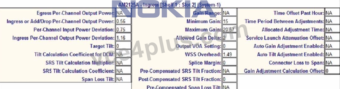
- A. -0.02 to 1.14 dB
- B. -0.6 to 1.72 dB
- C. 0.56 to 1.14 dB
- D. 0.56 to 1.72 dB
Answer: B
Explanation:
Explanation
The available output optical power range is the difference between the maximum gain and the minimum gain range of the ingress amplifier. According to the EPT Power Management Report, the maximum gain is 25.7 dB and the minimum gain range is 14 dB. Therefore, the available output optical power range is 25.7 - 14 =
11.7 dB. To convert this to a logarithmic scale, we use the formula 10^(x/10), where x is the value in dB.
Therefore, the available output optical power range in logarithmic scale is 10^(11.7/10) - 10^(14/10) = 14.68 -
25.12 = -0.6 to 1.72dB. References : Nokia Optical Diagnostics and Troubleshooting Course | Nokia, EPT Power Management Report | Nokia
NEW QUESTION # 17
Suppose a "Channel Absent" alarm is reported on an 1830 PSS node. What is the recommended order for the following troubleshooting steps?
- A. 1. Retrieve the channel power trace.
2. Retrieve the cross-connection (XC) details and see what Wave Keys should be present.
3. Go to the suspected troubled node / card / port and look at Wave Keys (in / out).
4. Check observed Wave Keys against expected Wave Keys. - B. 1. Go to the suspected troubled node / card / port and look at Wave Keys (in / out).
2. Retrieve the cross-connection (XC) details and see what Wave Keys should be present.
3. Check observed Wave Keys against expected Wave Keys.
4. Retrieve the channel power trace. - C. 1. Check observed Wave Keys against expected Wave Keys.
2. Go to the suspected troubled node / card / port and look at Wave Keys (in / out).
3. Retrieve the channel power trace.
4. Retrieve the cross-connection (XC) details and see what Wave Keys should be present. - D. 1. Retrieve the cross-connection (XC) details and see what virave Keys should be present.
2. Go to the suspected troubled node / card / port and look at Wave Keys (in / out).
3. Retrieve the channel power trace.
4. Check observed Wave Keys against expected Wave Keys.
Answer: A
Explanation:
Explanation
The recommended order for the troubleshooting steps is B, as follows:
* Retrieve the channel power trace. This step is useful to identify the affected channel and its power level, as well as to check if there are any fluctuations or anomalies in the power trace that could indicate a channel absent issue1.
* Retrieve the cross-connection (XC) details and see what Wave Keys should be present. This step is necessary to verify which Wave Keys are expected to be present on the node, card, and port based on the XC configuration2. Wave Keys are unique identifiers for wavelength tracking that are encoded by Optical Transponders (OTs) into each service wavelength direction3.
* Go to the suspected troubled node / card / port and look at Wave Keys (in / out). This step is helpful to compare the observed Wave Keys with the expected Wave Keys, and to locate the source of the problem. If a Wave Key is missing or mismatched, it means that there is a channel absent issue on that node, card, or port4.
* Check observed Wave Keys against expected Wave Keys. This step is the final solution to resolve the issue and restore the normal operation of the node. The observed Wave Keys should match the expected Wave Keys based on the XC configuration. If not, the XC configuration should be corrected or the faulty node, card, or port should be replaced5. References : Nokia Optical Diagnostics and Troubleshooting Course | Nokia, Optical User Guide - Nokia, Alcatel-Lucent 1830 PSS-8 and PSS-16 Photonic Service Switch
NEW QUESTION # 18
A power adjustment has succeeded conditionally because of gain settings set to higher levels than expected by design. Which of the following alarms will raise?
- A. Power Adjustment Failure (PWRADJFAIL)
- B. Gain Adjustment Exceeded Max Value (PWRMAXGAIN)
- C. Amplifier Gain Tilt Adjustments Suspended (PWRTILTSUSP)
- D. Invalid topology (PRCDRERR-TOPO)
Answer: C
Explanation:
Explanation
A power adjustment has succeeded conditionally because of gain settings set to higher levels than expected by design. This means that the optical power levels of the amplifier have been adjusted within the acceptable range, but the gain values are higher than the design values. This can cause a performance degradation or instability of the optical signal. The alarm that will raise in this case is "Amplifier Gain Tilt Adjustments Suspended" (PWRTILTSUSP). This alarm indicates that the gain tilt adjustments, which are used to compensate for the wavelength-dependent loss of the optical signal, have been suspended due to high gain values. The alarm also suggests lowering the gain values manually or using the EPT tool. The other alarms are incorrect because they either indicate a different type of power adjustment issue or do not exist. References: Nokia Optical Diagnostics and Troubleshooting Course, OAM and Diagnostics Guide
NEW QUESTION # 19
Which of the following statements about optical power vs amplification stages is TRUE?
- A. When multiple channels pass through a shared port (for example, an amplifier line interface), the total aggregated power reflects the number of channels currently present.
- B. When channels pass through amplifiers, all of them always experience a similar amplification.
- C. Ingress amplifiers are always more powerful [than egress amplifiers, to reduce the impact of non-linear effects.
- D. The Optical Supervisory Channel (OSC) is amplified when passing through all amplifier types, except for Raman which is not based on EDFA.
Answer: A
Explanation:
Explanation
The statement that when multiple channels pass through a shared port (for example, an amplifier line interface), the total aggregated power reflects the number of channels currently present is TRUE. This means that the more channels are present, the higher the total output power will be, and vice versa. This is because each channel contributes to the total power by its own power level, and the amplifier tries to maintain a constant gain for each channel2. Therefore, the total output power depends on both the input power and the number of channels3. References : Nokia Optical Diagnostics and Troubleshooting Course | Nokia, Optical amplifiers, explained by RP; optical amplification, Amplifier chains, explained by RP; amplifier stages, preamplifier ...
NEW QUESTION # 20
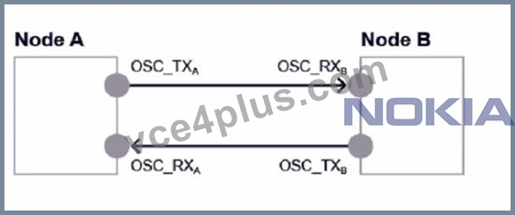
Consider the exhibit. Given the following power readings, what is the calculated span loss from Node A to Node B?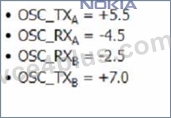
- A. 1.5
- B. 11.5
- C. 2.5
- D. 8.0
Answer: D
Explanation:
Explanation
The exhibit shows a diagram of a network with two nodes, Node A and Node B, connected by a fiber span.
The diagram also shows the power readings at different points of the span. The calculated span loss from Node A to Node B is the difference between the output power at Node A and the input power at Node B. According to the diagram, the output power at Node A is +3.5 dBm and the input power at Node B is -4.5 dBm.
Therefore, the span loss from Node A to Node B is 3.5 - (-4.5) = 8.0 dB.
NEW QUESTION # 21
When troubleshooting possible generic fiber cuts, the recommended first step is to: 1. Review alarms at nodes where power loss occurs.
What is the next recommended step?
- A. Review EPT design for calculated span loss.
- B. Review PM data to determine if the problem is intermittent.
- C. Monitor amplifier total power in/out to isolate the direction of a possible cut.
- D. Perform network power traces to attempt to determine the point of power loss.
Answer: D
Explanation:
Explanation
When troubleshooting possible generic fiber cuts, the recommended first step is to review alarms at nodes where power loss occurs. This can help identify the location and extent of the fiber cut and the affected services. The next recommended step is to perform network power traces to attempt to determine the point of power loss. Network power traces are graphical representations of the optical power levels along a span or a path. They can be used to compare the measured power levels with the expected power levels and to pinpoint any significant deviations or drops that indicate a fiber cut. The other options are incorrect because they either do not help locate the fiber cut or are not as effective as network power traces. References: Nokia Optical Diagnostics and Troubleshooting Course, OAM and Diagnostics Guide
NEW QUESTION # 22
Which of the following is a passive component in a CDC-F network configuration?
- A. MSH4-FSB Fiber Shuffle Module
- B. 130SCX10 Optical Transponder
- C. WR20-TFM Wavelength Router
- D. IRDM20 Integrated ROADM
Answer: A
Explanation:
Explanation
A passive component in a CDC-F network configuration is the MSH4-FSB Fiber Shuffle Module. This module is used to rearrange the fibers between the CDC-F modules and the wavelength routers, so that each wavelength router can access any of the 96 wavelengths in the C-band. The MSH4-FSB module does not require any power or active components, and it does not perform any optical amplification or switching2. References : Nokia Optical Diagnostics and Troubleshooting Course | Nokia, Nokia 1830 Photonic Service Switch (PSS) | Nokia
NEW QUESTION # 23
Consider the exhibit. What do the different colored green columns indicate?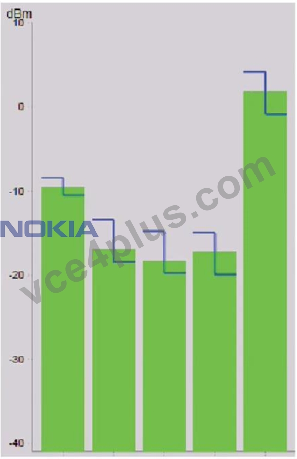
- A. Optical power levels measured for multiple wavelengths against a specific interface.
- B. The average optical power levels measured for multiple wavelengths throughout their shared optical path.
- C. Optical power levels measured multiple times against a specific interface, at 24-hour intervals for the same wavelength.
- D. Optical power levels measured at different interfaces throughout the optical path of a single wavelength.
Answer: D
Explanation:
Explanation
The exhibit shows a graph of optical power levels measured at different interfaces throughout the optical path of a single wavelength. The different colored green columns indicate the optical power levels at different points along the optical path, such as the transmitter, the receiver, and the amplifiers. The graph also shows the expected power levels and the allowed deviation range for each point. The graph can be used to monitor the performance and quality of the optical signal and to identify any potential issues or anomalies. The other options are incorrect because they either describe a different type of graph or do not match the exhibit. References: Nokia Optical Diagnostics and Troubleshooting Course, OAM and Diagnostics Guide
NEW QUESTION # 24
Which of the following statements about the "config powermgmt egress 1/2 adjust status command" is TRUE?
- A. The command displays the status of power adjustment on the specified egress amplifier.
- B. The command enables power adjustment feature on the specified egress amplifier.
- C. The command displays commissioning status and WT decoder usage for the specified egress amplifiers only, as this feature is always and only done in the egress direction.
- D. The command enables power adjustment feature on the specified egress amplifier, as this feature Is always and only available at the egress amplification stage.
Answer: B
Explanation:
Explanation
The command config powermgmt egress 1/2 adjust status is used to enable or disable the power adjustment feature on the specified egress amplifier. The power adjustment feature is a function that automatically adjusts the output power of an amplifier to compensate for changes in the input power or the number of channels. This feature can be enabled or disabled on both ingress and egress amplifiers, depending on the network configuration and requirements1. Therefore, the statement C is true. References : Nokia Optical Diagnostics and Troubleshooting Course | Nokia
NEW QUESTION # 25
Which of the following issues can cause a "Loss too low" message to be displayed after a power adjustment has been provided?
- A. A dirty fiber connector
- B. A defective WSS unit
- C. An incorrect EPT network design
- D. Unstable optical power levels
Answer: D
Explanation:
Explanation
A "Loss too low" message can be displayed after a power adjustment has been provided if there is an issue with unstable optical power levels. Unstable optical power levels can be caused by various factors, such as environmental conditions, fiber aging, equipment malfunction, or configuration errors. Unstable optical power levels can affect the accuracy and reliability of the power adjustment process, which relies on measuring the optical loss between two points in the network. A "Loss too low" message means that the measured optical loss is lower than the expected value, which can indicate a problem with the optical signal quality or integrity.
The other issues are incorrect because they either cause a different type of message or do not affect the power adjustment process. References: Nokia Optical Diagnostics and Troubleshooting Course, OAM and Diagnostics Guide
NEW QUESTION # 26
On a bidirectional optical amplifier configuration, which of the following are Wavelength Tracker detection points?
- A. An optical amplifier has no Wavelength Tracker detection points.
- B. LINEOUT and SIGOUT interfaces.
- C. LINE and SIG interfaces.
- D. SIG interface only.
Answer: C
Explanation:
Explanation
On a bidirectional optical amplifier configuration, the Wavelength Tracker detection points are the LINE and SIG interfaces. The Wavelength Tracker is a feature that monitors the wavelength of each channel on the optical amplifier and provides feedback to the control system. The Wavelength Tracker can detect wavelength drifts, channel failures, or channel additions or removals on both directions of the optical amplifier. The LINE interface is the input/output port for the optical line signal, while the SIG interface is the input/output port for the optical signal from/to the transponder. The other options are incorrect because the LINEOUT and SIGOUT interfaces are not Wavelength Tracker detection points, and an optical amplifier has Wavelength Tracker detection points. References: Nokia Optical Diagnostics and Troubleshooting Course, OAM and Diagnostics Guide
NEW QUESTION # 27
Consider the exhibit which shows an EPT Power Management Report referring to an ingress amplifier. What is the available output optical power range?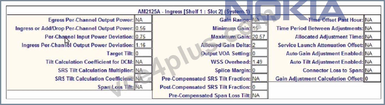
- A. -0.02 to 1.14 dB
- B. -0.6 to 1.72 dB
- C. 0.56 to 1.14 dB
- D. 0.56 to 1.72 dB
Answer: B
Explanation:
Explanation
The available output optical power range is the same as in question 5, since the EPT Power Management Report refers to the same ingress amplifier with the same settings and parameters. Therefore, the answer is also A, -0.6 to 1.72 dB. References : Nokia Optical Diagnostics and Troubleshooting Course | Nokia, EPT Power Management Report | Nokia
NEW QUESTION # 28
Which of the following correctly describes how a unidirectional amplification stage works?
- A. * Incoming optical signals are boosted by the ingress amplifier.
* Outgoing optical signals are also boosted by the ingress amplifier. - B. * Incoming optical signals are boosted by the ingress amplifier.
* Outgoing optical signals pass through the ingress amplifier but are not boosted. - C. * Incoming optical signals are boosted by the ingress amplifier.
* Outgoing optical signals do not pass through the ingress amplifier. - D. * Incoming optical signals pass through the ingress amplifier but are not boosted.
* Outgoing optical signals are boosted by the ingress amplifier.
Answer: C
Explanation:
Explanation
A unidirectional amplification stage works by boosting the incoming optical signals by the ingress amplifier, while the outgoing optical signals do not pass through the ingress amplifier. This means that the ingress amplifier only amplifies the signals in one direction, hence the name unidirectional. This configuration is typically used for point-to-point links or ring networks where bidirectional amplification is not required or desired1. References : Nokia Optical Diagnostics and Troubleshooting Course | Nokia
NEW QUESTION # 29
Which of the following statements about using Nokia product documentation in the troubleshooting process is TRUE?
- A. Before investigating a problem it is important to check the Engineering and Planning Tool User Guide (EPTUG) if a possible issue has already been acknowledged by the Product Unit (PU).
- B. Before investigating a problem it is important to check the User Provisioning Guide (UPG) if a possible issue has already been acknowledged by the Product Unit (PU).
- C. The Customer Release Notes (CRNs) document collects documented solved known issues, new issues discovered after the product software has been released.as well as software upgrade procedures and firmware details.
- D. The Customer Release Notes (CRNs) provides instructions to perform the automated provisioning, commissioning, and power balancing functions in a customer network based on the Nokia 1830 PS5 platform.
Answer: C
Explanation:
Explanation
The Customer Release Notes (CRNs) document collects documented solved known issues, new issues discovered after the product software has been released, as well as software upgrade procedures and firmware details. This document is useful for troubleshooting because it can help identify if a problem is related to a known issue or a software bug, and if there is a workaround or a solution available. The CRNs also provide information about the software compatibility and interoperability of different Nokia products and platforms.
The other options are incorrect because the EPTUG and the UPG do not contain information about known issues, and the CRNs do not provide instructions for automated provisioning, commissioning, and power balancing functions. References: Nokia Optical Diagnostics and Troubleshooting Course, Nokia Optical Diagnostics and Troubleshooting Exam
NEW QUESTION # 30
Consider the exhibit. A single directional fiber cut is occurring between two amplifiers in unidirectional configuration with Raman pump.
Multiple services are crossing the affected span.
Which node(s) will report an Incoming Payload LOS" alarm?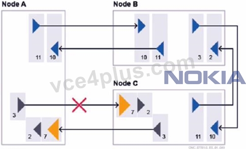
- A. Node C only.
- B. No node, as a Raman pump is used in Node A.
- C. Both Node A and Node C
- D. Neither Node A nor Node C.
Answer: C
Explanation:
Explanation
A single directional fiber cut is occurring between two amplifiers in unidirectional configuration with Raman pump. Multiple services are crossing the affected span. The node(s) that will report an Incoming Payload LOS alarm are both Node A and Node C. An Incoming Payload LOS alarm indicates that there is no or very low signal at the input port of a node. In the exhibit, Node A will report this alarm because it will not receive any signal from Node B due to the fiber cut. Node C will also report this alarm because it will not receive any signal from Node D due to the fiber cut. The Raman pump in Node A does not prevent this alarm, as it only amplifies the signal in the forward direction, not the backward direction. The other options are incorrect because they either ignore one of the nodes that will report the alarm or assume that the Raman pump has an effect on the backward direction. References: Nokia Optical Diagnostics and Troubleshooting Course, OAM and Diagnostics Guide
NEW QUESTION # 31
......
Get up-to-date Real Exam Questions for 4A0-265: https://www.vce4plus.com/Nokia/4A0-265-valid-vce-dumps.html
Pass 4A0-265 Exam Latest Practice Questions: https://drive.google.com/open?id=1khlX6QS59uOWV0ZmJa-ILJ73M1FEiAeT